Table of Contents
Thoughts on Cluster Network / Future Growth
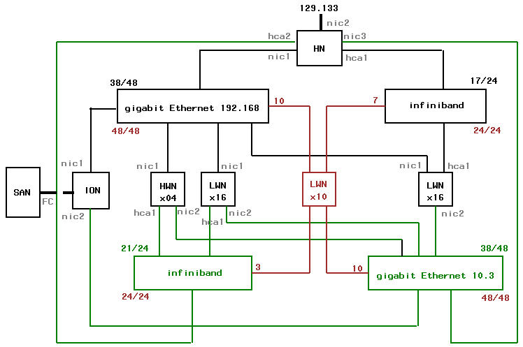
As i'm working my way through some of the Platform/OCS documentation provided, some thoughts came up that i want to keep track of. This page is not intended to detail how the cluster's final configuration will look like, but could act as a guideline. So first, the big picture. Drawn in black is the cluster as ordered, drawn in green the connections if additional switches were bought, which leads to the red drawings, the additional nodes that could be added based on green. Detailed commentary below.
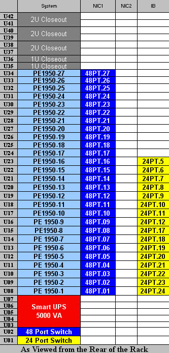
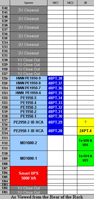
It was interesting to note where Dell installs the 2 switches in their rack layout:
in Rack #1, slots U01 (Infiniband) & U02 (gigabit ethernet) ... for ease of cabling
in Rack #2, slots U01 & U02 ... are left empty, this provides for an upgrade path
And that got me thinking about design issues, sparking this pre-delivery configuration ramble.
Summary Update (with thanks to wes faulty/researchers, platform.com and dell.com):
I arrived at a puzzle. Suddenly it appeared to me the head node had an HBA card (allows connections to the Infiniband switch). And rooting through the delivery box i found a 9' infiniband cable (marked 4X, all infiniband compute nodes have 1X cables).
So i looked at the design: the head node is always depicted connected to the infiniband switch. Perhaps it should be the ionode server ? But the 4X cables does not match the 1X connectors. So i threw the question back to dell & platform. here is the result of that:
#1 To connect a head node, or ionode, to the infiniband swith is trying to exploit the computational power of either, iow, users will need to be able to log in plus you'll allow computations that can essentially crash or overload that unit.
#2 IPoIB, we were warned about this, too experimental. We will only be using IB for parallel code messaging not IP level of traffic (NFS, SSH, etc).
The HBA card appears to be hot swappable so i'm just going to leave it as is.
— Henk Meij 2007/04/10 09:44
[in black] Configuration Details
- HN = Head Node
- NIC1 129.133
- NIC2 198.162
- / (contains /installs/rocks-dist & /state/partition1, on first hard disk)
- /localscratch (2nd hard disk? not sure, could just be off root if dual disks are striped)
- io node:/home
- io node:/sanscratch
- user logins permitted
- frequent backups
- firewall shield
The head node (front-end-0-0) is attached to 2 networks. NIC1 provides connectivity with 129.133.xxx.xxx (wesleyan.edu). Users would login into the head node from their desktops (subnets 88-95). VPN access would be required for off-campus access, including from subnet 8. Protocols such as ssh, sftp, bbftp, and http/https would be enabled, the local firewall would restrict all other access. Logins from the head node to other nodes would be restricted to administrative users only.
DHCP, http/https, 411 and other Platform/OCS tools would be installed in local file systems such as /opt/lava etc. The operating system software managed is located in local file system /install/rocks-dist. Other local file systems will exist such as /state/partition1 which is mounted on every compute node as /export/share (and not destroyed during future upgrades of the head node).
During the ROCKS installation, only the first hard disk will be used. These are 80 Gb disks, spinning at 7,200 RPM. All nodes on this cluster contain two hard disks except for the heavy weight nodes. Only the first will be used. So one idea might be to create a /localscratch area to complement the SAN scratch area mounted on /sanscratch (which presumably will be much faster).
Remote file systems, such as /home and /sanscratch are mounted from the io node via NFS. NIC2 is connected to the private network gigabit switch. The head node will communicate with the Infiniband enabled compute nodes via adapter HCA1 (not tcp/ip based).
- ION = IO Node
- NIC1 198.122
- NIC2 off
- / (contains only operating system)
- second hard disk idle
- LUN from SAN via fiber channel for /home
- LUN from SAN via fiber channel for /sanscratch
- user logins not permitted
- infrequent backups
The io node services the cluster two file systems via NFS. These file systems appear local to the io node via fiber channel (FC) from the SAN network attached storage devices (currently two NetApp clustered servers). The home directories (/home, backed up how?) projected at 10 terabytes, and the SAN based scratch space for the compute nodes (/sanscratch, not backed up), projected at ? ?bytes.
NIC1 provides the connectivity with the private network (198.162.xxx.xxx) and serves all NFS traffic to all compute nodes (4 heavy weight, 16 light weight, and 16 light weight on Infiniband; a total of 36 nodes) plus the NFS requirements of the head node. This could potentially be a bottle neck.
If the backup plan materializes for the /home file systems, it seems logical that the io node would the involved. However, maybe it's feasible to rely on the SAN snapshot capabilities with a very thin policy (as in a single snapshot per day …). Not sure.
- HWN = Heavy Weight Node
- NIC1 198.162
- NIC2 off
- / (contains operating system on first hard disk)
- 2nd hard disk: not installed
- /localscratch (mounted filesystem from MD1000)
- MD1000 storage device with split backplanes (each node access to 7 36 Gb disks spinning at 15,000 RPM, Raid 0)
- io node:/home
- io node:/sanscratch
- head node:/export/share
- user logins not permitted
- no backup
The only distinction between “heavy” and “light” weight compute nodes are the memory footprint and attached fast scratch disk space. The heavy weight nodes contain 16 Gb of memory versus the default 4 Gb. Two MD1000 (not shown), with backsplanes split, will serve dedicated local (fast) scratch space to the heavy weight nodes (/localscratch).
If we mount the scratch space on /localscratch, file references can remain the same across heavy and light weight nodes. Each /localscratch file system is dedicated to each node avoiding conflicts (not a clustered file system).
/home and /sanscratch are mounted from the io node using NFS via NIC1.
- LWN = Light Weight Node
- NIC1 198.162
- NIC2 off
- one group of 16 nodes with HCA1 adapter installed
- / (contains operating system on first hard disk)
- /localscratch (2nd hard disk)
- io node:/home
- io node:/sanscratch
- head node:/export/share
- user logins not permitted
- no backup
There are two groups of light weight nodes each comprised of 16 nodes. One group is connected to the Infiniband (and thus also the head node) switch via adapter HCA1. This implies we will have two queues for the light weight group i think. And possibly a third group combining all light weight nodes for non-parallel jobs involving up to 32 nodes. (Actually the heavy weight could be included i guess).
In both groups the /home and /sanscratch filesystems are mounted via NFS over the private network (NIC1). /localscratch is again the single spindle second hard disk. It's probably important to point out that /localscratch from the second hard disk is local to the nodes. /sanscratch, which is shared underneath all nodes, is not and users should be aware of the potential for conflicts. Any requirements for file locking and removal/creation of files should be staged in directories like /sanscratch/username/hostname/ created by the relevant programs. (maybe the directory creation and removal can be automated in the job scheduler as a pre-post execute step …)
[in green] Separating Administrative and NFS traffic
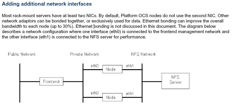
From the Platform/OCS User Guide
ok then, a 30% bandwidth improvement to each node is worth the investigation. Since it is so common, this is why Dell left those slots empty (i actually confirmed this with Dell). We should fill those slots from the start ![]() (btw ethernet bonding is applied in almost all of wesleyan's linux based servers).
(btw ethernet bonding is applied in almost all of wesleyan's linux based servers).
If a second private network is added, lets say 10.3.xxx.xxx, we could turn on all those idle NIC2 interfaces (see drawing, no purchases necessary other than cables & switch). All compute nodes would be connected to this second (48 port) gigabit ethernet switch via NIC2. The io node also has an idle NIC2 interface, so it is connected too. The head node, a Power Edge 2950 blade, would need an additional interface card, NIC3, which needs to be purchased. The Power Edge 2950 supports this configuration (checked Dell's web site).
In this configuration then, all NFS related traffic could be forced through the 10.3 private network. That would separate this traffic from administrative traffic and greatly alleviate the potential bottlenecks. It would also greatly help the io node.
so then, why stop there? The need for a second Infiniband switch would probably be driven by user requirements needing access to a larger pool of Infiniband enabled nodes. Its addition to the cluster network has the great advantage of simplifying the design of the scheduler queues. If a 24 port Infiniband switch were added, all heavy weight nodes and all light weight nodes not yet connected could be connected via HCA#1 (needs purchasing). In addition the head node would need to be connected via HCA#2 (could not find out if this is supported, alternatively can the Infiniband switches themselves be connected directly?)
If this design is implemented, the gigabit ethernet switches would each have 38 ports occupied out of 48. The Infiniband switches would have 17 and 21 ports occupied (see drawing). Which leads us to the red scribbles.
[in red] Potential Expansion
Scheming along, the question then presents itself: How many nodes could be added so that all port switches are in use? Answer = 10.
The 10 additional nodes, let's assume light weight nodes (drawn in red, see drawing), can all be connected to both gigabit ethernet switches. Connecting those nodes to the infiniband is more complicated; 7 go to the first switch and 3 to the second switch. This may pose a problem cabling wise.
Rack #1 has 8 available 1U slots, so after stashing in 7 new nodes, the nodes are connected to both switches located in that rack (that would leave one 1U slot available in the rack).
Rack #2, has 16 available 1U slots, so after stashing in 3 new nodes, the nodes are connected to both switches in that rack (leaving 13 available 1U slots in the rack).
Then, the 7 nodes from rack #1 need to be connected to the gigabit ethernet switch in rack #2, and the 3 new nodes in rack #2 need to be connected to the gigabit ethernet switch in rack #1. Hehe.
Presto, should be possible. Power supply wise this should be ok. That leaves a total of 14 available 1U slots … more nodes, yea!, drawn in white ![]()
Rack Layout
Please note that i have modified the original drawings for clarity and also suppressed all the power distribution and supply connections. Just imagine a lot of cable. Also, the io node (one of the PE 2950s) is shown as connected to the Infiniband switch but i'm guessing that is not correct.
The compute nodes are all Power Edge 1950 servers occupying 1U of rack space each.
The head node and io node are Power Edge 2950 servers occupying 2U of rack space each.
As a reminder, the Final Configuration Page.
| Links to Dell's web site for detailed information | |
|---|---|
| Power Edge 1950 | Power Edge 2950 |


